Secure Locking
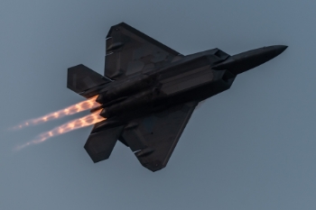
Secure your RF connectors, adapters, and cable assemblies in harsh environments with this suite of carefully designed and selected RF interconnects. The presence of environmental shock and vibration can negatively affect RF performance by causing two mated connectors to become loose and, in some cases, disconnect. SV's products below are ideal for harsh environments, with Secure Locking product lines like Threaded SMPM, Quarterback®, and Keyed SMA Cable Assemblies.
Designed with locking features, additional screws, and mating captivation, this suite of products is ideal when RF is used in applications like:
Launch conditions
Travel over rugged terrain
Space flight
Military / Avionics
Features / Benefits:
- Variety of options for additional mating security
- Custom mechanical features provide extra captivation during mating
- Variety of threaded and push-on interfaces
- Available through distribution
- DC - 67 GHz
Applications:
- Mil/Aero
- Commercial
- Space
- Power dividers and combiners
- Transceiver Box
1.85 mm
| Impedance (Ω) | 50 |
| Frequency GHz | 65 GHz |
| Shielding Effectiveness | ≥ -100 dB |
| Dielectric withstanding Voltage | 500 VRMS |
| Mating Cycles | 500 |
| Mating Torque | 5 - 7 in - lbs |
| Inter-mate ability | 2.4mm |
| Temperature Rating | -65°C to +165°C |
| Corrosion (salt spray) | MIL-STD-202, Method 101, Condition B |
| Vibration | MIL-STD-202, Method 204, Condition D |
| Shock | MIL-STD-202, Method 213, Condition I |
| Thermal Shock | MIL-STD-202, Method 107, Condition B |
| Moisture Resistance | MIL-STD-202, Method 106, Less Step 7B |
| Barometric Pressure (Altitude) | MIL-STD-202, Method 105, Condition C, 70k Ft. |
2.4 mm
| Impedance (Ω) | 50 |
| Frequency GHz | 50 GHz |
| Shielding Effectiveness | ≥ -100 dB |
| Dielectric withstanding Voltage | 500 VRMS |
| Mating Cycles | 500 |
| Mating Torque | 5 - 7 in - lbs |
| Inter-mate ability | 1.85mm |
| Temperature Rating | -65°C to +165°C |
| Corrosion (salt spray) | MIL-STD-202, Method 101, Condition B |
| Vibration | MIL-STD-202, Method 204, Condition D |
| Shock | MIL-STD-202, Method 213, Condition I |
| Thermal Shock | MIL-STD-202, Method 107, Condition B |
| Moisture Resistance | MIL-STD-202, Method 106, Less Step 7B |
| Barometric Pressure (Altitude) | MIL-STD-202, Method 105, Condition C, 70k Ft. |
2.92 mm
| Impedance (Ω) | 50 |
| Frequency GHz | 40 GHz |
| Shielding Effectiveness | ≥ -100 dB |
| Dielectric withstanding Voltage | 750 VRMS |
| Mating Cycles | 500 |
| Mating Torque | 7 - 10 in - lbs |
| Inter-mate ability | SMA |
| Temperature Rating | -65°C to +165°C |
| Corrosion (salt spray) | MIL-STD-202, Method 101, Condition B |
| Vibration | MIL-STD-202, Method 204, Condition D |
| Shock | MIL-STD-202, Method 213, Condition I |
| Thermal Shock | MIL-STD-202, Method 107, Condition B |
| Moisture Resistance | MIL-STD-202, Method 106, Less Step 7B |
| Barometric Pressure (Altitude) | MIL-STD-202, Method 105, Condition C, 70k Ft. |
SMA
| Impedance (Ω) | 50 |
| Frequency GHz | 18 GHz (select models to 26.5 GHz) |
| Shielding Effectiveness | ≥ -90 dB |
| Dielectric withstanding Voltage | 1000 VRMS |
| Mating Cycles | 500 |
| Mating Torque | 7 - 10 in - lbs |
| Inter-mate ability | 2.92mm |
| Temperature Rating | -65°C to +165°C |
| Corrosion (salt spray) | MIL-STD-202, Method 101, Condition B |
| Vibration | MIL-STD-202, Method 204, Condition D |
| Shock | MIL-STD-202, Method 213, Condition I |
| Thermal Shock | MIL-STD-202, Method 107, Condition B |
| Moisture Resistance | MIL-STD-202, Method 106, Less Step 7B |
| Barometric Pressure (Altitude) | MIL-STD-202, Method 105, Condition C, 70k Ft. |
SMP
| Impedance (Ω) | 50 |
| Frequency GHz | 40 GHz |
| Shielding Effectiveness | ≥ -80 dB DC - 3 GHz ≥ -65 dB 3 - 26.5 GHz |
| Dielectric withstanding Voltage | 500 VRMS |
| Mating Cycles - SB | 1000 |
| Mating Cycles - LD | 500 |
| Mating Cycles - FD | 100 |
| Insertion Force - SB | 3.0 lbs |
| Insertion Force - LD | 5.0 lbs |
| Insertion Force - FD | 7.0 lbs |
| Withdrawal Force - SB | 0.5 lbs |
| Withdrawal Force - LD | 7.0 lbs |
| Withdrawal Force - FD | 9.0 lbs |
| Axial Misalignment | .010” Max |
| Radial Misalignment | 3° Max |
| Temperature Rating | -65°C to +165°C |
| Corrosion (salt spray) | MIL-STD-202, Method 101, Condition B |
| Vibration | MIL-STD-202, Method 204, Condition D |
| Shock | MIL-STD-202, Method 213, Condition I |
| Thermal Shock | MIL-STD-202, Method 107, Condition B |
| Moisture Resistance | MIL-STD-202, Method 106, Less Step 7B |
| Barometric Pressure (Altitude) | MIL-STD-202, Method 105, Condition C, 70k Ft. |
SMPM
| Impedance (Ω) | 50 |
| Frequency GHz | 65 GHz |
| Shielding Effectiveness | ≥ -80 dB DC - 3 GHz ≥ -65 dB 3 - 26.5 GHz |
| Dielectric withstanding Voltage | 325 VRMS |
| Mating Cycles - SB | 500 |
| Mating Cycles - FD | 100 |
| Insertion Force - SB | 2.5 lbs |
| Insertion Force - FD | 4.5 lbs |
| Withdrawal Force - SB | 1.5 lbs |
| Withdrawal Force - FD | 6.5 lbs |
| Axial Misalignment | .010” Max |
| Radial Misalignment | 3° Max |
| Temperature Rating | -65°C to +165°C |
| Corrosion (salt spray) | MIL-STD-202, Method 101, Condition B |
| Vibration | MIL-STD-202, Method 204, Condition D |
| Shock | MIL-STD-202, Method 213, Condition I |
| Thermal Shock | MIL-STD-202, Method 107, Condition B |
| Moisture Resistance | MIL-STD-202, Method 106, Less Step 7B |
| Barometric Pressure (Altitude) | MIL-STD-202, Method 105, Condition C, 70k Ft. |
SMPS
| Impedance (Ω) | 50 |
| Frequency GHz | 65 GHz |
| Shielding Effectiveness | ≥ -80 dB DC - 3 GHz ≥ -65 dB 3 - 26.5 GHz |
| Dielectric withstanding Voltage | 250 VRMS |
| Mating Cycles - SB | 500 |
| Mating Cycles - FD | 100 |
| Insertion Force - SB | 1.2 lbs |
| Insertion Force - FD | 2.5 lbs |
| Withdrawal Force - SB | 1.0 lbs |
| Withdrawal Force - FD | 4.5 lbs |
| Axial Misalignment | .010” Max |
| Radial Misalignment | 3° Max |
| Temperature Rating | -65°C to +165°C |
| Corrosion (salt spray) | MIL-STD-202, Method 101, Condition B |
| Vibration | MIL-STD-202, Method 204, Condition D |
| Shock | MIL-STD-202, Method 213, Condition I |
| Thermal Shock | MIL-STD-202, Method 107, Condition B |
| Moisture Resistance | MIL-STD-202, Method 106, Less Step 7B |
| Barometric Pressure (Altitude) | MIL-STD-202, Method 105, Condition C, 70k Ft. |
ZMA
| Impedance (Ω) | 50 |
| Frequency GHz | 18 GHz |
| Shielding Effectiveness | ≥ -90 dB |
| Dielectric withstanding Voltage | 2500 VRMS |
| Mating Cycles | 500 |
| Mating Torque | 4 in - oz |
| Temperature Rating | -65°C to +165°C |
| Corrosion (salt spray) | MIL-STD-202, Method 101, Condition B |
| Vibration | MIL-STD-202, Method 204, Condition D |
| Shock | MIL-STD-202, Method 213, Condition I |
| Thermal Shock | MIL-STD-202, Method 107, Condition B |
| Moisture Resistance | MIL-STD-202, Method 106, Less Step 7B |
| Barometric Pressure (Altitude) | MIL-STD-202, Method 105, Condition C, 70k Ft. |
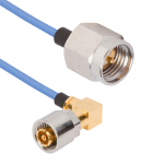
Part # 7032-9896
Threaded SMPM Female R/A to SMA Male 12" Cable Assembly for .047 Cable
Available Inventory: 60
7032-9896
SMPM Cable Assemblies 7032-9896
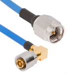
Part # 7032-9894
Threaded SMPM Female R/A to SMA Male 12" Cable Assembly for .085 Cable
Available Inventory: 76
7032-9894
SMPM Cable Assemblies 7032-9894
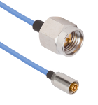
Part # 7032-9895
Threaded SMPM Female to SMA Male 12" Cable Assembly for .047 Cable
Available Inventory: 96
7032-9895
SMPM Cable Assemblies 7032-9895
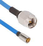
Part # 7032-9893
Threaded SMPM Female to SMA Male 12" Cable Assembly for .085 Cable
Available Inventory: 85
7032-9893
SMPM Cable Assemblies 7032-9893


