


High Speed Edge Launch PCB Connectors
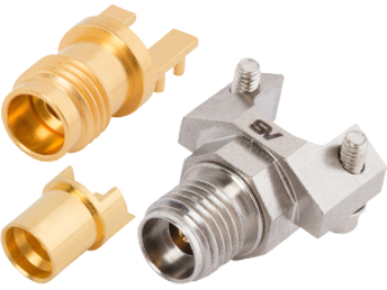
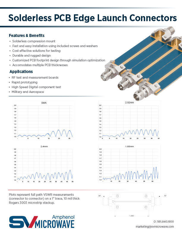
SV offers a complete line of extreme frequency (DC - 100 GHz) coaxial / RF edge launch PCB connectors that meet the need for high performing, highly reliable precision connectors. Current RF test connector configurations include single and multiport 2.92 mm, 2.4 mm, 1.85 mm, SMA, SMP, SMPM and SMPS variations. SV Microwave’s SMP, SMPM & SMPS coaxial PCB connector designs are ideal for high density applications while allowing for axial and radial misalignment to compensate for tolerance stack up. Get custom PCB footprint designs to optimize connector to PCB transitions.
Features / Benefits:
- High frequency RF performance up to 40 GHz (2.92mm version)
- Durable and rugged design
- Low profile PCB connector design has an overall smaller footprint
Applications:
- High speed/frequency component test
- Product evaluation boards
- Mil-Aero radar and communication systems
- Satellite communication systems
The specifications below are typical for the connector series, but may not apply to this particular part. Please see the datasheet for full specifications.
1.85 mm
| Impedance (Ω) | 50 |
| Frequency GHz | 65 GHz |
| Shielding Effectiveness | ≥ -100 dB |
| Dielectric withstanding Voltage | 500 VRMS |
| Mating Cycles | 500 |
| Mating Torque | 5 - 7 in - lbs |
| Inter-mate ability | 2.4mm |
| Temperature Rating | -65°C to +165°C |
| Corrosion (salt spray) | MIL-STD-202, Method 101, Condition B |
| Vibration | MIL-STD-202, Method 204, Condition D |
| Shock | MIL-STD-202, Method 213, Condition I |
| Thermal Shock | MIL-STD-202, Method 107, Condition B |
| Moisture Resistance | MIL-STD-202, Method 106, Less Step 7B |
| Barometric Pressure (Altitude) | MIL-STD-202, Method 105, Condition C, 70k Ft. |
2.4 mm
| Impedance (Ω) | 50 |
| Frequency GHz | 50 GHz |
| Shielding Effectiveness | ≥ -100 dB |
| Dielectric withstanding Voltage | 500 VRMS |
| Mating Cycles | 500 |
| Mating Torque | 5 - 7 in - lbs |
| Inter-mate ability | 1.85mm |
| Temperature Rating | -65°C to +165°C |
| Corrosion (salt spray) | MIL-STD-202, Method 101, Condition B |
| Vibration | MIL-STD-202, Method 204, Condition D |
| Shock | MIL-STD-202, Method 213, Condition I |
| Thermal Shock | MIL-STD-202, Method 107, Condition B |
| Moisture Resistance | MIL-STD-202, Method 106, Less Step 7B |
| Barometric Pressure (Altitude) | MIL-STD-202, Method 105, Condition C, 70k Ft. |
2.92 mm
| Impedance (Ω) | 50 |
| Frequency GHz | 40 GHz |
| Shielding Effectiveness | ≥ -100 dB |
| Dielectric withstanding Voltage | 750 VRMS |
| Mating Cycles | 500 |
| Mating Torque | 7 - 10 in - lbs |
| Inter-mate ability | SMA |
| Temperature Rating | -65°C to +165°C |
| Corrosion (salt spray) | MIL-STD-202, Method 101, Condition B |
| Vibration | MIL-STD-202, Method 204, Condition D |
| Shock | MIL-STD-202, Method 213, Condition I |
| Thermal Shock | MIL-STD-202, Method 107, Condition B |
| Moisture Resistance | MIL-STD-202, Method 106, Less Step 7B |
| Barometric Pressure (Altitude) | MIL-STD-202, Method 105, Condition C, 70k Ft. |
SMA
| Impedance (Ω) | 50 |
| Frequency GHz | 18 GHz (select models to 26.5 GHz) |
| Shielding Effectiveness | ≥ -90 dB |
| Dielectric withstanding Voltage | 1000 VRMS |
| Mating Cycles | 500 |
| Mating Torque | 7 - 10 in - lbs |
| Inter-mate ability | 2.92mm |
| Temperature Rating | -65°C to +165°C |
| Corrosion (salt spray) | MIL-STD-202, Method 101, Condition B |
| Vibration | MIL-STD-202, Method 204, Condition D |
| Shock | MIL-STD-202, Method 213, Condition I |
| Thermal Shock | MIL-STD-202, Method 107, Condition B |
| Moisture Resistance | MIL-STD-202, Method 106, Less Step 7B |
| Barometric Pressure (Altitude) | MIL-STD-202, Method 105, Condition C, 70k Ft. |
SMP
| Impedance (Ω) | 50 |
| Frequency GHz | 40 GHz |
| Shielding Effectiveness | ≥ -80 dB DC - 3 GHz ≥ -65 dB 3 - 26.5 GHz |
| Dielectric withstanding Voltage | 500 VRMS |
| Mating Cycles - SB | 1000 |
| Mating Cycles - LD | 500 |
| Mating Cycles - FD | 100 |
| Insertion Force - SB | 3.0 lbs |
| Insertion Force - LD | 5.0 lbs |
| Insertion Force - FD | 7.0 lbs |
| Withdrawal Force - SB | 0.5 lbs |
| Withdrawal Force - LD | 7.0 lbs |
| Withdrawal Force - FD | 9.0 lbs |
| Axial Misalignment | .010” Max |
| Radial Misalignment | 3° Max |
| Temperature Rating | -65°C to +165°C |
| Corrosion (salt spray) | MIL-STD-202, Method 101, Condition B |
| Vibration | MIL-STD-202, Method 204, Condition D |
| Shock | MIL-STD-202, Method 213, Condition I |
| Thermal Shock | MIL-STD-202, Method 107, Condition B |
| Moisture Resistance | MIL-STD-202, Method 106, Less Step 7B |
| Barometric Pressure (Altitude) | MIL-STD-202, Method 105, Condition C, 70k Ft. |
SMPM
| Impedance (Ω) | 50 |
| Frequency GHz | 65 GHz |
| Shielding Effectiveness | ≥ -80 dB DC - 3 GHz ≥ -65 dB 3 - 26.5 GHz |
| Dielectric withstanding Voltage | 325 VRMS |
| Mating Cycles - SB | 500 |
| Mating Cycles - FD | 100 |
| Insertion Force - SB | 2.5 lbs |
| Insertion Force - FD | 4.5 lbs |
| Withdrawal Force - SB | 1.5 lbs |
| Withdrawal Force - FD | 6.5 lbs |
| Axial Misalignment | .010” Max |
| Radial Misalignment | 3° Max |
| Temperature Rating | -65°C to +165°C |
| Corrosion (salt spray) | MIL-STD-202, Method 101, Condition B |
| Vibration | MIL-STD-202, Method 204, Condition D |
| Shock | MIL-STD-202, Method 213, Condition I |
| Thermal Shock | MIL-STD-202, Method 107, Condition B |
| Moisture Resistance | MIL-STD-202, Method 106, Less Step 7B |
| Barometric Pressure (Altitude) | MIL-STD-202, Method 105, Condition C, 70k Ft. |
SMPS
| Impedance (Ω) | 50 |
| Frequency GHz | 65 GHz |
| Shielding Effectiveness | ≥ -80 dB DC - 3 GHz ≥ -65 dB 3 - 26.5 GHz |
| Dielectric withstanding Voltage | 250 VRMS |
| Mating Cycles - SB | 500 |
| Mating Cycles - FD | 100 |
| Insertion Force - SB | 1.2 lbs |
| Insertion Force - FD | 2.5 lbs |
| Withdrawal Force - SB | 1.0 lbs |
| Withdrawal Force - FD | 4.5 lbs |
| Axial Misalignment | .010” Max |
| Radial Misalignment | 3° Max |
| Temperature Rating | -65°C to +165°C |
| Corrosion (salt spray) | MIL-STD-202, Method 101, Condition B |
| Vibration | MIL-STD-202, Method 204, Condition D |
| Shock | MIL-STD-202, Method 213, Condition I |
| Thermal Shock | MIL-STD-202, Method 107, Condition B |
| Moisture Resistance | MIL-STD-202, Method 106, Less Step 7B |
| Barometric Pressure (Altitude) | MIL-STD-202, Method 105, Condition C, 70k Ft. |
ZMA
| Impedance (Ω) | 50 |
| Frequency GHz | 18 GHz |
| Shielding Effectiveness | ≥ -90 dB |
| Dielectric withstanding Voltage | 2500 VRMS |
| Mating Cycles | 500 |
| Mating Torque | 4 in - oz |
| Temperature Rating | -65°C to +165°C |
| Corrosion (salt spray) | MIL-STD-202, Method 101, Condition B |
| Vibration | MIL-STD-202, Method 204, Condition D |
| Shock | MIL-STD-202, Method 213, Condition I |
| Thermal Shock | MIL-STD-202, Method 107, Condition B |
| Moisture Resistance | MIL-STD-202, Method 106, Less Step 7B |
| Barometric Pressure (Altitude) | MIL-STD-202, Method 105, Condition C, 70k Ft. |
Application Note
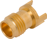
Part # 3321-60001
1.85mm Female PCB Edge Launch Connector, .062" PCB Thickness
Available Inventory: 171
3321-60001
1.85mm Connectors 3321-60001
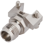
Part # SF3321-60021
1.85mm Female Solderless PCB Edge Launch Connector, 2 Hole
Available Inventory: 151
SF3321-60021
1.85mm Connectors SF3321-60021
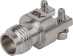
3321-60059
1.85mm Connectors 3321-60059
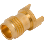
1621-60008
2.4mm Connectors 1621-60008
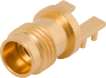
1621-60050
2.4mm Connectors 1621-60050
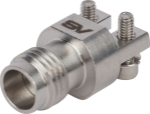
1621-60075
2.4mm Connectors 1621-60075
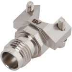
Part # SF1621-60036
2.4mm Female Solderless PCB Edge Launch Connector, 2 Hole
Available Inventory: 110
SF1621-60036
2.4mm Connectors SF1621-60036
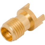
Part # 1521-60051
2.92mm Female PCB Edge Launch Connector, .062" PCB Thickness
Available Inventory: 791
1521-60051
2.92mm Connectors 1521-60051
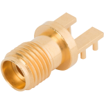
1521-00002
2.92mm Connectors 1521-00002
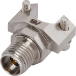
Part # SF1521-60107
2.92mm Female Solderless PCB Edge Launch Connector, 2 Hole
Available Inventory: 523
SF1521-60107
2.92mm Connectors SF1521-60107
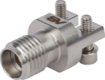
Part # 1521-60201
2.92mm Female Solderless PCB Edge Launch Connector, 2 Hole
Available Inventory: 1295
1521-60201
2.92mm Connectors 1521-60201
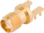
2921-61493
SMA Connectors 2921-61493
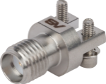
2921-61674
SMA Connectors 2921-61674
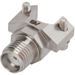
SF2921-61450
SMA Connectors SF2921-61450
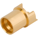
Part # 1285-6002
SMP Male PCB Edge Launch Connector, .062" PCB Thickness, FD
Available Inventory: 1291
1285-6002
SMP Connectors 1285-6002
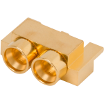
3211-60087
SMPM Connectors 3211-60087

3285-6001
SMPM Connectors 3285-6001
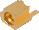
3811-40003
SMPS Connectors 3811-40003
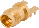
3321-60065
3321-60065 1.85mm Connector