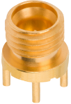


Single Port Reflow Stable PCB Connectors with Legs
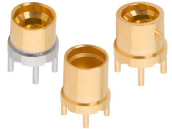
SV Microwave has released a new line of incredibly rugged and durable surface-mount PCB connectors in the SMP, SMPM, and SMPS series. Alongside our standard surface pin contacts, this product line also features extended length thru-pins that are soldered directly into the board to establish a stronger mechanical connection. All configurations include four solderable legs to secure the connector and prevent damage to solder joints or traces during demating.
A glass seal dielectric maintains dimensional stability during high-temperature solder reflow and captivates the pin to prevent rotation. Lastly, pre-tinned connector options are also available to protect the solder joint from gold embrittlement in high-reliability applications.
Features & Benefits
- Standard Surface & Extended Thru-pin options
- Glass seal dielectric maintains dimensional stability during solder reflow
- Pre-tinned connector options available
- Mechanical legs for a stronger connection to the PCB
Applications
- High-Reliability Space and Satellite Communications
- Defense Radar Systems
- Hypersonic flight environment
The specifications below are typical for the connector series, but may not apply to this particular part. Please see the datasheet for full specifications.
SMP
| Impedance (Ω) | 50 |
| Frequency GHz | 40 GHz |
| Shielding Effectiveness | ≥ -80 dB DC - 3 GHz ≥ -65 dB 3 - 26.5 GHz |
| Dielectric withstanding Voltage | 500 VRMS |
| Mating Cycles - SB | 1000 |
| Mating Cycles - LD | 500 |
| Mating Cycles - FD | 100 |
| Insertion Force - SB | 3.0 lbs |
| Insertion Force - LD | 5.0 lbs |
| Insertion Force - FD | 7.0 lbs |
| Withdrawal Force - SB | 0.5 lbs |
| Withdrawal Force - LD | 7.0 lbs |
| Withdrawal Force - FD | 9.0 lbs |
| Axial Misalignment | .010” Max |
| Radial Misalignment | 3° Max |
| Temperature Rating | -65°C to +165°C |
| Corrosion (salt spray) | MIL-STD-202, Method 101, Condition B |
| Vibration | MIL-STD-202, Method 204, Condition D |
| Shock | MIL-STD-202, Method 213, Condition I |
| Thermal Shock | MIL-STD-202, Method 107, Condition B |
| Moisture Resistance | MIL-STD-202, Method 106, Less Step 7B |
| Barometric Pressure (Altitude) | MIL-STD-202, Method 105, Condition C, 70k Ft. |
SMPM
| Impedance (Ω) | 50 |
| Frequency GHz | 65 GHz |
| Shielding Effectiveness | ≥ -80 dB DC - 3 GHz ≥ -65 dB 3 - 26.5 GHz |
| Dielectric withstanding Voltage | 325 VRMS |
| Mating Cycles - SB | 500 |
| Mating Cycles - FD | 100 |
| Insertion Force - SB | 2.5 lbs |
| Insertion Force - FD | 4.5 lbs |
| Withdrawal Force - SB | 1.5 lbs |
| Withdrawal Force - FD | 6.5 lbs |
| Axial Misalignment | .010” Max |
| Radial Misalignment | 3° Max |
| Temperature Rating | -65°C to +165°C |
| Corrosion (salt spray) | MIL-STD-202, Method 101, Condition B |
| Vibration | MIL-STD-202, Method 204, Condition D |
| Shock | MIL-STD-202, Method 213, Condition I |
| Thermal Shock | MIL-STD-202, Method 107, Condition B |
| Moisture Resistance | MIL-STD-202, Method 106, Less Step 7B |
| Barometric Pressure (Altitude) | MIL-STD-202, Method 105, Condition C, 70k Ft. |
SMPS
| Impedance (Ω) | 50 |
| Frequency GHz | 65 GHz |
| Shielding Effectiveness | ≥ -80 dB DC - 3 GHz ≥ -65 dB 3 - 26.5 GHz |
| Dielectric withstanding Voltage | 250 VRMS |
| Mating Cycles - SB | 500 |
| Mating Cycles - FD | 100 |
| Insertion Force - SB | 1.2 lbs |
| Insertion Force - FD | 2.5 lbs |
| Withdrawal Force - SB | 1.0 lbs |
| Withdrawal Force - FD | 4.5 lbs |
| Axial Misalignment | .010” Max |
| Radial Misalignment | 3° Max |
| Temperature Rating | -65°C to +165°C |
| Corrosion (salt spray) | MIL-STD-202, Method 101, Condition B |
| Vibration | MIL-STD-202, Method 204, Condition D |
| Shock | MIL-STD-202, Method 213, Condition I |
| Thermal Shock | MIL-STD-202, Method 107, Condition B |
| Moisture Resistance | MIL-STD-202, Method 106, Less Step 7B |
| Barometric Pressure (Altitude) | MIL-STD-202, Method 105, Condition C, 70k Ft. |
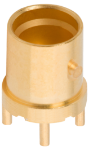
Part # 1211-66493
SMP Male PCB QB Surface Mount Connector (Glass Seal) SB, 4 Legs
Available Inventory: 0
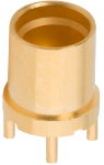
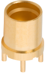
Part # 1211-66490
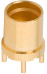
SMP Male PCB Surface Mount Connector (Glass Seal) FD, Thru Pin, 4 Legs
Available Inventory: 0
Part # 1211-66489
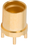
SMP Male PCB Surface Mount Connector (Glass Seal) SB, Thru Pin, 4 Legs
Available Inventory: 0
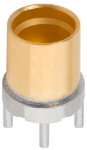
Part # 1211-66492
SMP Male PCB Surface Mount Connector (Glass Seal, Pre-Tinned) FD, 4 Legs
Available Inventory: 0
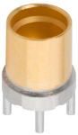
Part # 1211-66491
SMP Male PCB Surface Mount Connector (Glass Seal, Pre-Tinned) SB, 4 Legs
Available Inventory: 0
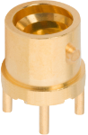
Part # 3211-60529
SMPM Male PCB QB Surface Mount Connector (Glass Seal) SB, 4 Legs
Available Inventory: 0
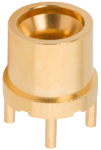
Part # 3211-60524
SMPM Male PCB Surface Mount Connector (Glass Seal) FD, 4 Legs
Available Inventory: 0
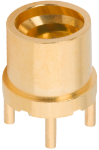
Part # 3211-60526
SMPM Male PCB Surface Mount Connector (Glass Seal) FD, Thru Pin, 4 Legs
Available Inventory: 0
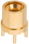
Part # 3211-60523
SMPM Male PCB Surface Mount Connector (Glass Seal) SB, 4 Legs
Available Inventory: 0
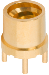
Part # 3211-60525
SMPM Male PCB Surface Mount Connector (Glass Seal) SB, Thru Pin, 4 Legs
Available Inventory: 0
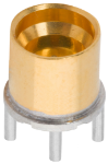
Part # 3211-60528
SMPM Male PCB Surface Mount Connector (Glass Seal, Pre-Tinned) FD, 4 Legs
Available Inventory: 0
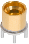
Part # 3211-60527
SMPM Male PCB Surface Mount Connector (Glass Seal, Pre-Tinned) SB, 4 Legs
Available Inventory: 0
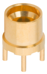
Part # 3811-60110
SMPS Male PCB Surface Mount Connector (Glass Seal) FD, 4 Legs
Available Inventory: 0
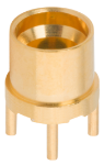
Part # 3811-60112
SMPS Male PCB Surface Mount Connector (Glass Seal) FD, Thru Pin, 4 Legs
Available Inventory: 0
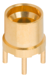
Part # 3811-60109
SMPS Male PCB Surface Mount Connector (Glass Seal) SB, 4 Legs
Available Inventory: 0
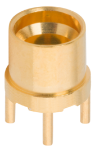
Part # 3811-60111
SMPS Male PCB Surface Mount Connector (Glass Seal) SB, Thru Pin, 4 Legs
Available Inventory: 0
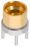
Part # 3811-60114
SMPS Male PCB Surface Mount Connector (Glass Seal, Pre-Tinned) FD, 4 Legs
Available Inventory: 0
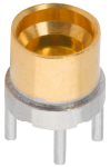
Part # 3811-60113
SMPS Male PCB Surface Mount Connector (Glass Seal, Pre-Tinned) SB, 4 Legs
Available Inventory: 0