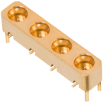


PCB Multiport With Right Angle Contact
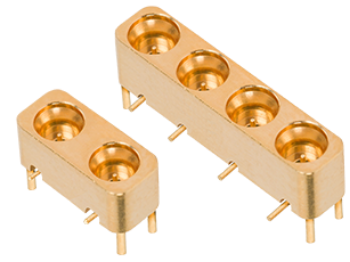
SV Microwave introduces our new RF PCB multiports with right-angle contacts. This product line offers a board-level solution to a common assembler need: inspection of a solder joint. Although the multiport connector has a straight body, it features a swept contact that exits the connector body at a right angle to the PCB trace. While still offering excellent RF performance from DC - 40 GHz, an operator can now visually inspect the solder joint, reducing the need for x-ray inspection or electrical testing to find solder defects.
Available in 2-port and 4-port configurations with SMPM and SMPS interfaces, this high-density PCB connector solution simplifies PCB trace mating without altering your standard multiport cable configurations.
Features & Benefits
- Direct Solder Joint Inspectability
- Available in SMPM and SMPS Interfaces
- DC – 40 GHz
Applications
- Mil-Aero
- EW Suites
- Radar Systems
- Cube Satellites and SmallSats
- Board-to-Board Applications
The specifications below are typical for the connector series, but may not apply to this particular part. Please see the datasheet for full specifications.
SMPM
| Impedance (Ω) | 50 |
| Frequency GHz | 65 GHz |
| Shielding Effectiveness | ≥ -80 dB DC - 3 GHz ≥ -65 dB 3 - 26.5 GHz |
| Dielectric withstanding Voltage | 325 VRMS |
| Mating Cycles - SB | 500 |
| Mating Cycles - FD | 100 |
| Insertion Force - SB | 2.5 lbs |
| Insertion Force - FD | 4.5 lbs |
| Withdrawal Force - SB | 1.5 lbs |
| Withdrawal Force - FD | 6.5 lbs |
| Axial Misalignment | .010” Max |
| Radial Misalignment | 3° Max |
| Temperature Rating | -65°C to +165°C |
| Corrosion (salt spray) | MIL-STD-202, Method 101, Condition B |
| Vibration | MIL-STD-202, Method 204, Condition D |
| Shock | MIL-STD-202, Method 213, Condition I |
| Thermal Shock | MIL-STD-202, Method 107, Condition B |
| Moisture Resistance | MIL-STD-202, Method 106, Less Step 7B |
| Barometric Pressure (Altitude) | MIL-STD-202, Method 105, Condition C, 70k Ft. |
SMPS
| Impedance (Ω) | 50 |
| Frequency GHz | 65 GHz |
| Shielding Effectiveness | ≥ -80 dB DC - 3 GHz ≥ -65 dB 3 - 26.5 GHz |
| Dielectric withstanding Voltage | 250 VRMS |
| Mating Cycles - SB | 500 |
| Mating Cycles - FD | 100 |
| Insertion Force - SB | 1.2 lbs |
| Insertion Force - FD | 2.5 lbs |
| Withdrawal Force - SB | 1.0 lbs |
| Withdrawal Force - FD | 4.5 lbs |
| Axial Misalignment | .010” Max |
| Radial Misalignment | 3° Max |
| Temperature Rating | -65°C to +165°C |
| Corrosion (salt spray) | MIL-STD-202, Method 101, Condition B |
| Vibration | MIL-STD-202, Method 204, Condition D |
| Shock | MIL-STD-202, Method 213, Condition I |
| Thermal Shock | MIL-STD-202, Method 107, Condition B |
| Moisture Resistance | MIL-STD-202, Method 106, Less Step 7B |
| Barometric Pressure (Altitude) | MIL-STD-202, Method 105, Condition C, 70k Ft. |
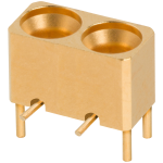
Part # 9312-40028
SMPM Male R/A Contact PCB Surface Mount Connector, 2 Port, SB
Available Inventory: 0
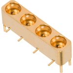
Part # 3212-40048
SMPM Male R/A Contact PCB Surface Mount Connector, 4 Port, FD
Available Inventory: 0
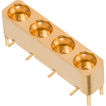
Part # 3212-40049
SMPM Male R/A Contact PCB Surface Mount Connector, 4 Port, SB
Available Inventory: 0
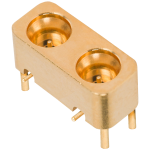
Part # 3812-40011
SMPS Male R/A Contact PCB Surface Mount Connector, 2 Port, FD
Available Inventory: 0
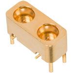
Part # 3812-40012
SMPS Male R/A Contact PCB Surface Mount Connector, 2 Port, SB
Available Inventory: 0
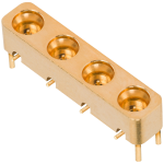
Part # 3812-40013
SMPS Male R/A Contact PCB Surface Mount Connector, 4 Port, FD
Available Inventory: 0