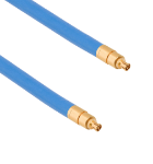


High Density Low Profile Cable Assemblies
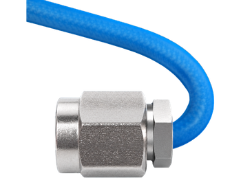
SV Microwave redefines tight-space RF routing with our next-generation Low Profile RF Cable Assemblies. In standard coaxial cable assemblies, a common failure point occurs from breakage caused by solder wicking. During assembly, molten solder can escape the primary joint between the connector and the cable. This solder travels up the outer braid via capillary action, where it cools and hardens. This unwanted metal flow stiffens the flexible assembly, creating a brittle zone that is highly susceptible to cracking, mechanical fatigue, and eventual electrical failure when bent.
We uses a proprietary design that prevents solder from extending beyond the rear of the connector body. Because the braid remains free of solder, the cable can bend immediately upon exiting the connector. Ideal for dense "inside-the-box" enclosures, these assemblies maintain optimal RF performance even when compressed by tight enclosure lids. Built with a high-durability steel outer braid, they provide superior mechanical strength, and perform reliably up to 40 GHz.
Features and Benefits
- Reduced/Eliminated Solder Wicking
- Immediate bends allowed upon exiting the connector body
- Steel outer braid increases tensile strength
- DC up to 40 GHz – even under tight routing conditions
Applications
- Rugged Chassis
- Tight Envelopes
- Inside the Box
- Radar and Electronic Warfare
- Satellite Systems
The specifications below are typical for the connector series, but may not apply to this particular part. Please see the datasheet for full specifications.
SMP
| Impedance (Ω) | 50 |
| Frequency GHz | 40 GHz |
| Shielding Effectiveness | ≥ -80 dB DC - 3 GHz ≥ -65 dB 3 - 26.5 GHz |
| Dielectric withstanding Voltage | 500 VRMS |
| Mating Cycles - SB | 1000 |
| Mating Cycles - LD | 500 |
| Mating Cycles - FD | 100 |
| Insertion Force - SB | 3.0 lbs |
| Insertion Force - LD | 5.0 lbs |
| Insertion Force - FD | 7.0 lbs |
| Withdrawal Force - SB | 0.5 lbs |
| Withdrawal Force - LD | 7.0 lbs |
| Withdrawal Force - FD | 9.0 lbs |
| Axial Misalignment | .010” Max |
| Radial Misalignment | 3° Max |
| Temperature Rating | -65°C to +165°C |
| Corrosion (salt spray) | MIL-STD-202, Method 101, Condition B |
| Vibration | MIL-STD-202, Method 204, Condition D |
| Shock | MIL-STD-202, Method 213, Condition I |
| Thermal Shock | MIL-STD-202, Method 107, Condition B |
| Moisture Resistance | MIL-STD-202, Method 106, Less Step 7B |
| Barometric Pressure (Altitude) | MIL-STD-202, Method 105, Condition C, 70k Ft. |
SMA
| Impedance (Ω) | 50 |
| Frequency GHz | 18 GHz (select models to 26.5 GHz) |
| Shielding Effectiveness | ≥ -90 dB |
| Dielectric withstanding Voltage | 1000 VRMS |
| Mating Cycles | 500 |
| Mating Torque | 7 - 10 in - lbs |
| Inter-mate ability | 2.92mm |
| Temperature Rating | -65°C to +165°C |
| Corrosion (salt spray) | MIL-STD-202, Method 101, Condition B |
| Vibration | MIL-STD-202, Method 204, Condition D |
| Shock | MIL-STD-202, Method 213, Condition I |
| Thermal Shock | MIL-STD-202, Method 107, Condition B |
| Moisture Resistance | MIL-STD-202, Method 106, Less Step 7B |
| Barometric Pressure (Altitude) | MIL-STD-202, Method 105, Condition C, 70k Ft. |
SMPM
| Impedance (Ω) | 50 |
| Frequency GHz | 65 GHz |
| Shielding Effectiveness | ≥ -80 dB DC - 3 GHz ≥ -65 dB 3 - 26.5 GHz |
| Dielectric withstanding Voltage | 325 VRMS |
| Mating Cycles - SB | 500 |
| Mating Cycles - FD | 100 |
| Insertion Force - SB | 2.5 lbs |
| Insertion Force - FD | 4.5 lbs |
| Withdrawal Force - SB | 1.5 lbs |
| Withdrawal Force - FD | 6.5 lbs |
| Axial Misalignment | .010” Max |
| Radial Misalignment | 3° Max |
| Temperature Rating | -65°C to +165°C |
| Corrosion (salt spray) | MIL-STD-202, Method 101, Condition B |
| Vibration | MIL-STD-202, Method 204, Condition D |
| Shock | MIL-STD-202, Method 213, Condition I |
| Thermal Shock | MIL-STD-202, Method 107, Condition B |
| Moisture Resistance | MIL-STD-202, Method 106, Less Step 7B |
| Barometric Pressure (Altitude) | MIL-STD-202, Method 105, Condition C, 70k Ft. |
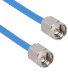
Part # 7029-8059
SMA Male to SMA Male Low Profile 12" Cable Assembly for .086 Cable
Available Inventory: 0
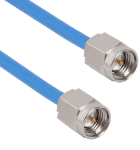
Part # 7029-8058
SMA Male to SMA Male Low Profile 6" Cable Assembly for .086 Cable
Available Inventory: 0
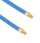
Part # 7012-4787
SMP Female to SMP Female Low Profile 12" Cable Assembly for .086 Cable
Available Inventory: 0
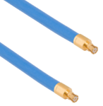
Part # 7012-4786
SMP Female to SMP Female Low Profile 6" Cable Assembly for .086 Cable
Available Inventory: 0
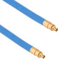
Part # 7032-10971
SMPM Female to SMPM Female Low Profile 12" Cable Assembly for .086 Cable
Available Inventory: 0